


PROGRAMMABLE LABORATORY SIGNAL ROUTING
SMX-8050A
40-channel programmable signal matrix with USB-C and front-panel operation. Route connections between external measurement instruments and selected device contacts using five banks of eight channels. Configure switching from a computer or directly using the integrated display and keypad.
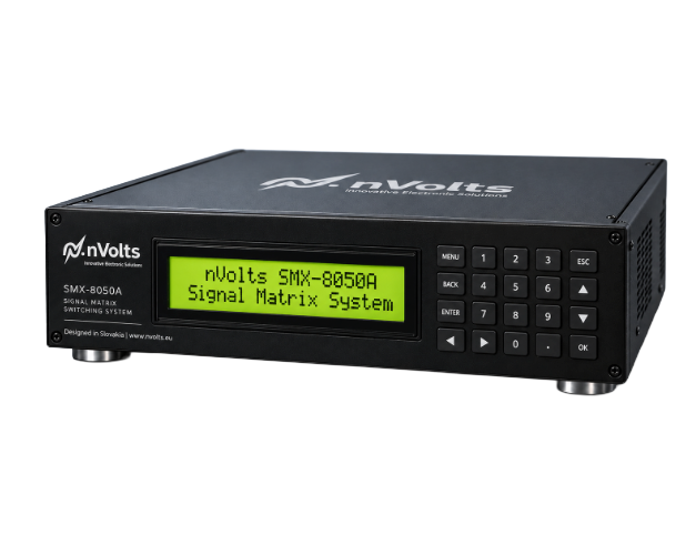
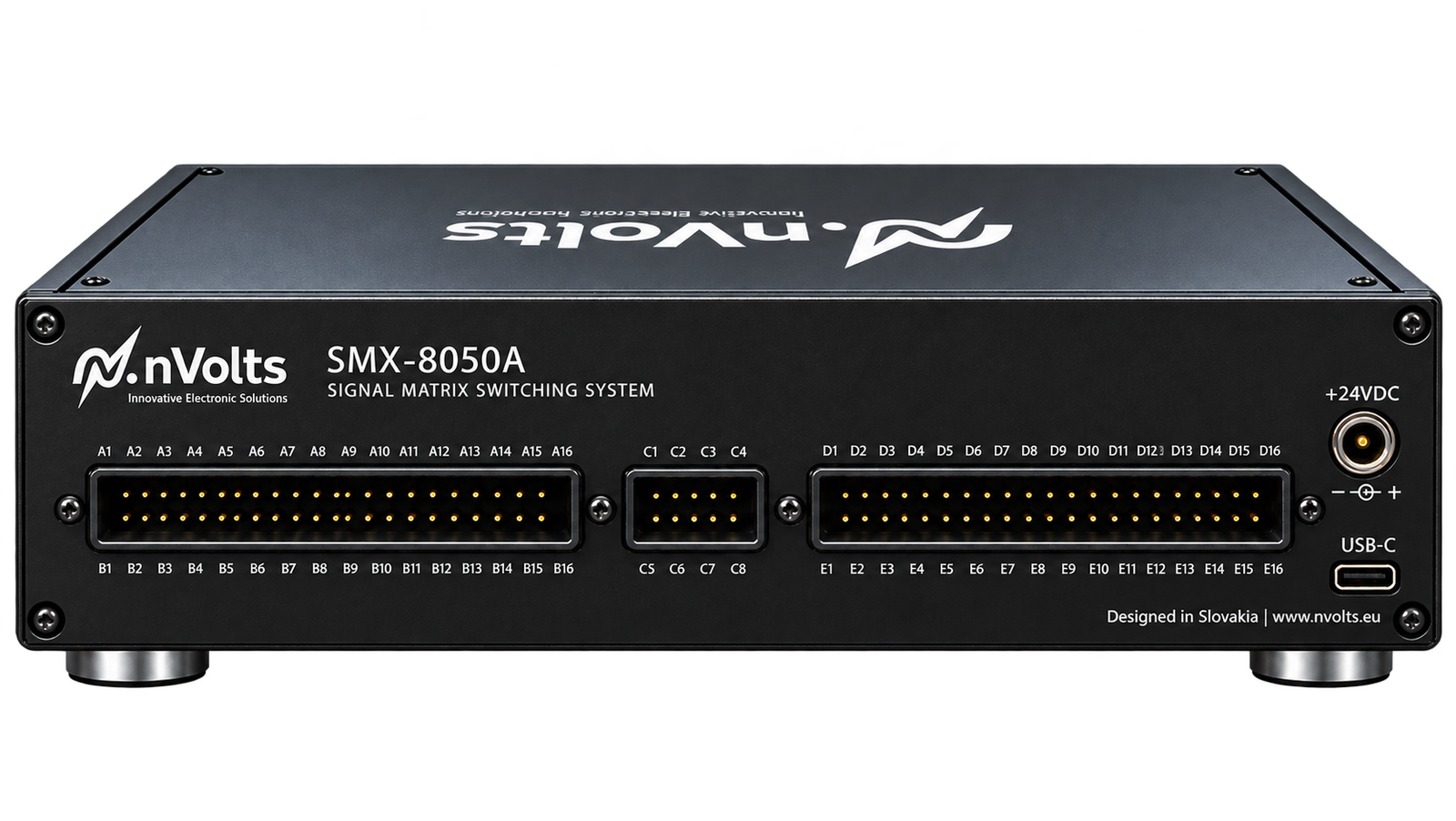
Five banks of eight signal paths
Key Capabilities
40 switching channels
Five banks with eight selectable switching channels each
Five independent banks
5 × 8 signal-routing architecture for DUT contact selection
Front-panel operation
Integrated LCD and keypad for local switching control
USB-C control
Computer-based matrix configuration and channel selection
Instrument routing
Connect an external source/measurement instrument to selected DUT contacts
Dual control options
Operate via USB-connected software or the built-in front-panel interface
Where Researchers Use the SMX-8050A
Automated Laboratory Switching
Connect an external source-measure instrument to selected test contacts using the SMX-8050A. Use a PC for automated routing or the integrated display and keypad for local operation.
Automated device testing
Switch between selected test points during repeatable measurement procedures.
Electrical characterization
Connect an external SMU or compatible instrument to different DUT terminals.
Sensor arrays & multi-contact devices
Address selected sensing elements or contacts without repeated manual cable changes.
Typical Laboratory Connection
The SMX-8050A routes selected signal connections between an external source-measure unit (SMU) and a device under test. Use USB-C for computer control or the built-in front-panel display and keypad for local operation. The external instrument generates and measures signals.
The SMX-8050A selects signal paths between the external instrument and device-under-test contacts.
Choose the contact pair
Select which device terminals should be connected through the matrix.
Route the signal
The switch matrix connects the selected pair to the external instrument.
Run the measurement
Use your source-measure instrument to acquire and record test data.
Technical Specifications & Integration
SMX-8050A combines 40-channel signal routing with USB-C computer control and integrated front-panel operation. The matrix selects connections, while external laboratory equipment performs excitation and measurement.
Switching Hardware
| Channel capacity | 40 selectable switching channels |
|---|---|
| Physical architecture | Five banks of eight switching channels |
| Bank arrangement | 5 × 8 switching channels |
| Local operation | Integrated LCD and keypad for front-panel selection |
| Signal function | Routes selected signals between an external instrument and DUT contacts |
Control & Integration
| Connection | USB Type-C computer control |
|---|---|
| PC control | Computer-based matrix control software |
| Integration | USB-controlled integration with external test applications |
| System requirements | Computer for routing control; external source/measurement instrument for electrical tests |
| Switching control | Select signal paths using USB software or the front-panel display and keypad |
Request a SMX-8050A Quotation
Need help choosing? Compare NCA analyzers and SMX switch matrices side by side.
Share your external instrument model, DUT contact layout, signal voltage and current, and required switching sequence. Tell us whether you need computer control, front-panel operation or both, along with quantity and target delivery date if known. We can review the configuration and prepare a quotation. See also SMX-8050, or explore the complete instrument range.
Planning an automated test? Read our SMX switch matrix measurement guide for bank selection, switching sequences and integration planning.